Connect of microcontroller to the Relay Circuit Diagram I'm working on a I/O module to control AC, DC motor and lamps by using relays. But I don't know how to control the relays. Some says I should use optocoupler, some says transistor array. I found an optocoupler TLP280, in the figure there is the schematic. Can I use it by supplying 3.3V to control 24V dc motor and some lambs.

Relays are devices which allow low power circuits to switch a relatively high Current and/or Voltage on/off. Here is a simple microcontroller-relay interface circuit with perfect "galvanic isolation". This post will outline how you can drive a relay using micro-controllers like AVR. Concepts are same for any other micro-controller used either in standalone mode or embedded in a development board like Netduino or Arduino. Before we begin, I want to introduce the relay to you. If you already know, then you can skip this section. What is a relay A relay is an electrical switch that turns on or

Relay Control Circuit Using 8051 Microcontroller Circuit Diagram
A microcontroller is a low-power logic device. By itself, it is generally incapable of directly driving a relay. A single N-channel MOSFET may be interposed between the microcontroller and relay to increase the available coil current and accommodate relays with higher coil voltages. In this article, we explore a simple MOSFET-based interface allowing an Arduino Nano Every to control a 12 VDC

The relay driver circuit using ULN2003 is given below. In this circuit diagram, the pic microcontroller is providing a signal to 4 relays through relay driver IC ULN2003.
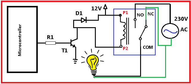
How to drive a relay using Microcontrollers Circuit Diagram
Electromechanical Relays construction and working principle, interfacing circuits with microcontroller using transistors and relay driver IC ULN2003 A relay control circuit is essential for controlling high-power devices using a low-power microcontroller. This project demonstrates how to use the 8051 microcontroller to control a relay, which can then switch on or off an external device such as a light bulb, motor, or fan. Relays act as electrically operated switches that isolate the control circuit from the high-power load, providing They can directly interface with microcontrollers due to their very low input current requirements. Therefore, solid-state relays are an ideal choice for microcontrollers and digital circuits.
